The Basic section lets you manage the basic settings of your print. The available settings in this section are:
Layer
Layer height
The layer height is the size of the Z increment for each layer. If you set this to 0.2mm, it means that after one layer is complete, the nozzle will move up .2mm to complete the next layer. The thickness of the layer will be of .2mm.
Infill
Infill pattern
The infill pattern defines the geometrical pattern the print will use to fill the space inside the print shell. You have different patterns available :

Grid: Selected by default. 45° oriented regular grid. Square and simple.

Hex: honeycomb style. It will build the infill based on a hexagon-shaped pattern.

Vase: The vase mode will remove the top and all the infill. The walls and bottom will be left untouched.

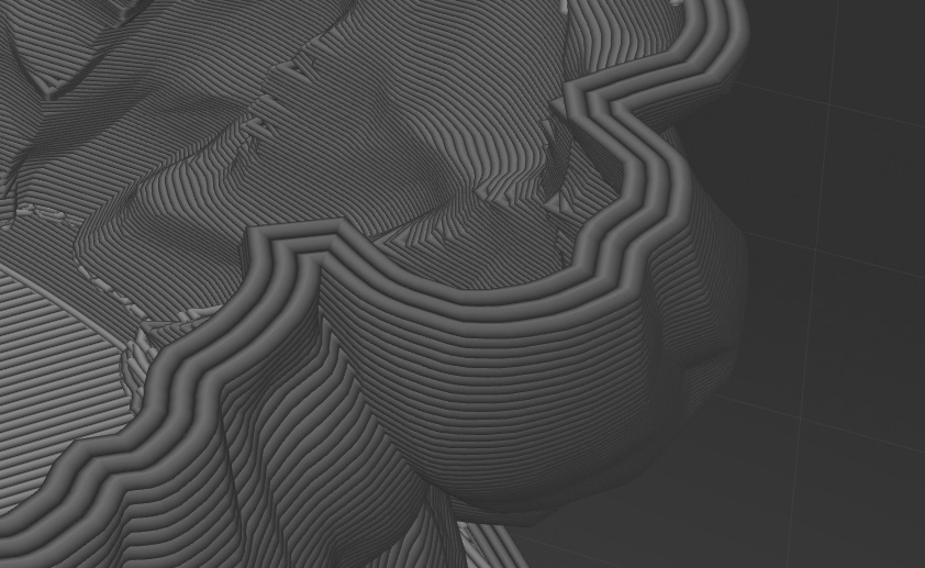
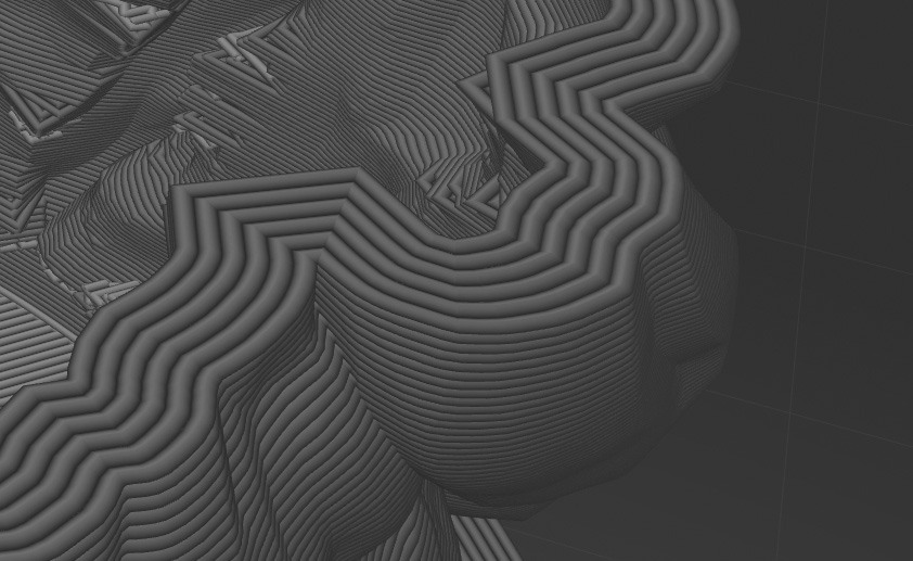
Gyroid: the infill will be made of tri-dimensional curves or waves. Although gyroid is the most time-consuming infill, it will provide high resistance to your piece since it brings almost isotropic mechanical properties to the structure of your print (stronger along the X/Y-axis but may be weaker on the Z-axis). Also, keep in mind that gyroid infill may impact the external appearance of your print.

Triangle: just like the grid, but intersecting at 60°. Basically, it will build an equilateral triangle grid if you prefer.
Linear: almost the same as grid, except that the “lines” of the grid do not cross each other on the same layer, they leap over each other: one layer is always oriented 90° to the preceding one.

Empty: you guessed it, there’s no filling inside the object, it will be a pure empty shell.

Full: as opposed to the Empty infill, the Full infill completely fills the inner space with material, which makes it a completely solid-filled print.
Infill density
The infill density is the “tightness” of the infill pattern. The denser it is, the tighter the pattern will be. The higher the value, the harder and the stiffer the print will be. Increasing the infill density will increase the global mechanical resistance of the printed object.
Usually, infill density varies from 20 to 50%. Below 20%, the shape will be mainly preserved, but mechanical performance will drop drastically, while over 50% infill will result in extensive print time and material consumption.
For more info and tips about infill type and density for your prints, read this article on best practices.
Solid

Solid sets the number of layers composing the shell of your print: the number of Bottom and Top layers, and the number of loops the printer will do to build the Walls of your print.
By controlling the thickness of your print’s “shell”, which builds up the outer faces of your print, you will control the global strength and hardness of the printed object. The thicker the shell is, the harder and the stiffer your print will be.
Top Layers
The amount of layers constituting the “ceiling and roof” of your object.
Bottom Layers
The amount of layers constituting the “flooring” of your object.
Walls
Walls mainly form the sides of your print.
Moreover
The differences between Walls and Top/Bottom layers lie in the very function of each feature.
The walls are everything that is not strictly horizontal and facing down or up from the object itself.
Bottoms and Tops are the upper and lower “caps” of your model. They are aimed to close the volume at their top and lower faces. Basically, the Bottom layers are laid on existing material while the Top layers are hanging and will need support.
In this set of figures, we’ll go through the Walls, Tops and Bottoms creation step by step.
Let’s consider a volume of a closed pot, with 4 layers of Top, 4 layers of Bottom, and 2 Walls.
First, the volume is created by constructing the Walls, and then, the Top and Bottom are added. At this point, we have Walls, Top closure, and Bottom closure. Let’s have a look at the structure of the volume.
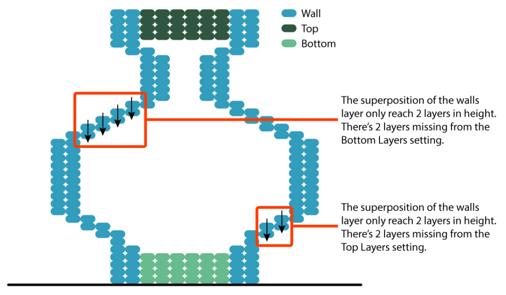
In order to meet the “4 Top Layers” and the “4 Bottom Layers”, some material has to be added. In the next figure, we will add Top and Bottom where it is needed, in order to meet the minimum required layers count.
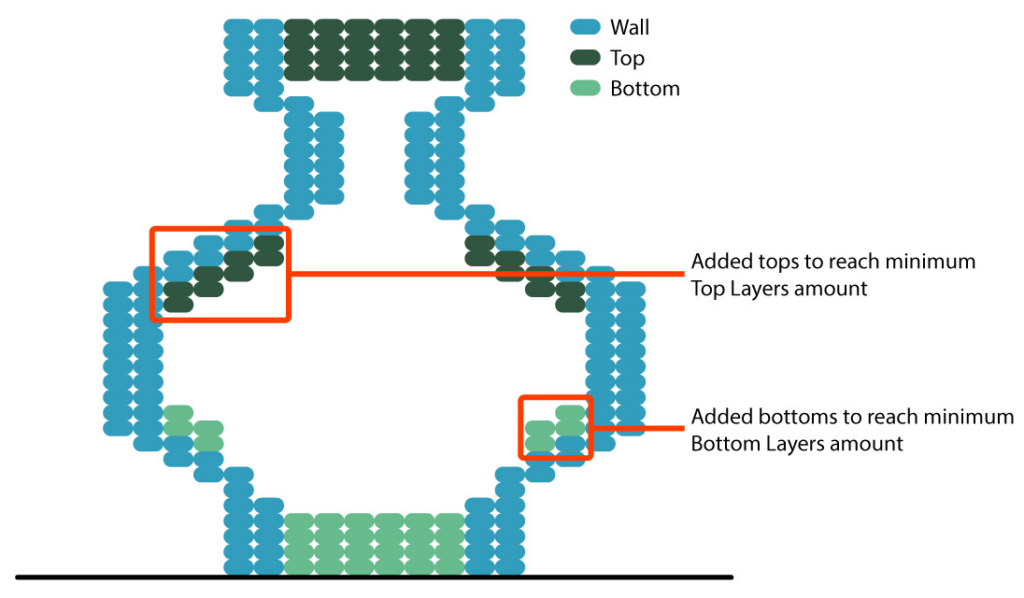
Once the missing layers are added, the infill and the supports may be added to fill in the gaps.
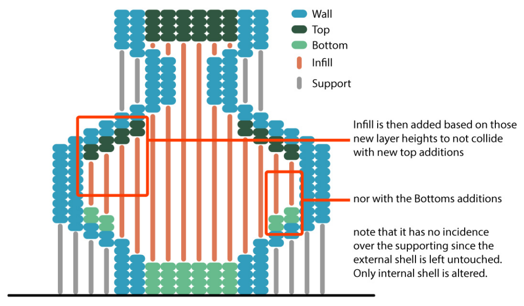
As you can see, Walls are not just made of Walls but are also made of bits of Tops and of Bottoms. Controlling the thickness of the shell will greatly improve the stiffness and hardness of your print. Knowing this will help you in tweaking your settings to meet specific needs when printing parts that may be subject to specific constraints.
Speed

The Max Print Speed defines the maximum speed at which the nozzle will travel during the print. The higher the number, the faster the printer will move the nozzle. The value is expressed in mm/s.
Just as a car, the engines (motors in this case) are designed to go to a certain maximum speed. Whatever you do, it will not go faster. Faster cars have bigger/faster engines, faster printers have bigger/faster motors.
It is important to set this properly. Keep in mind that this setting will have many effects on your print and every printer has its limitations.
Nozzle diameter brings limitations to printing speed as it bottlenecks the filament output. The thinner the nozzle, the slower the extrusion will be.
Speed will also be impacted by the hotend limitations since it will have to fuse the material in order to squeeze it in the nozzle and eventually extrude it quickly enough.
Printing too fast can lead to issues such as ghost printing (nothing is printed or parts of the print are missing), “Wobbly” prints (the layers are slightly shifted or are unevenly superposed)
You can access more advanced features and settings for your print (for all Layers, Infill, Solid and Speed settings) in the Advanced panel (the third thumbnail of the Override panel).
Last updated on